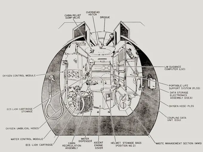
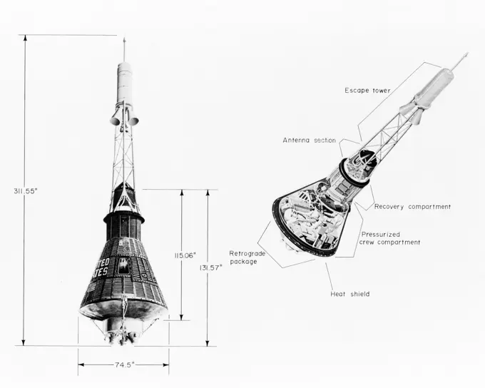
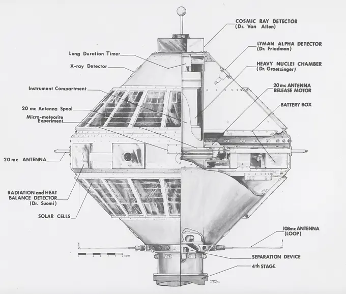
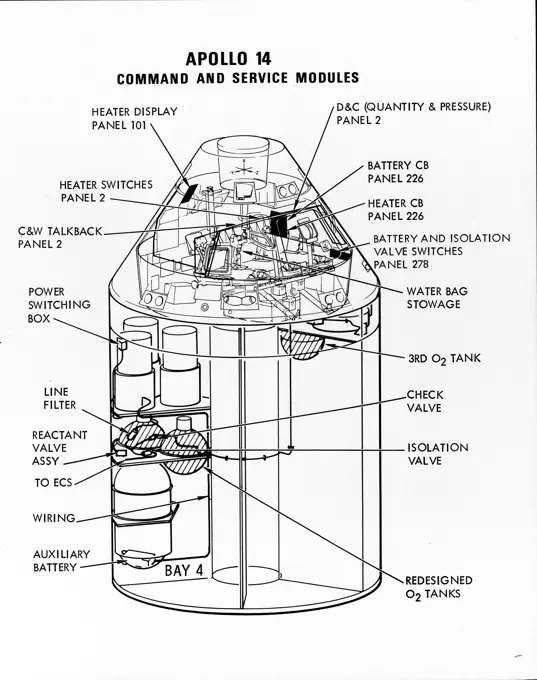
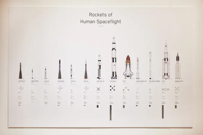
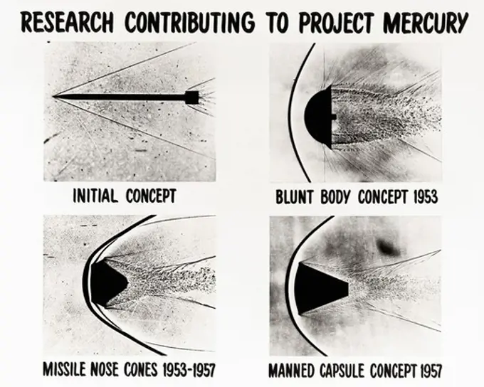
Fine ArtVintageFootageSubscriptionBoardsFree ResearchPricing
  • Fine Art
  • Vintage
  • Footage
  • Subscription
  • Boards
  • Free Research
  • Pricing

Spacecraft Design and Comparisons

Illustrations of different spacecraft designs, including Mercury and Apollo capsules, showcasing dimensions and structural details.

Lunar Module Ascent Stage Interior View Looking Aft
90 assets in this story
6145-44710505
S63-19317 (October 1963) --- Pen and ink views of comparative arrangements of several capsules including the existing Big Joe design, the compromise Big Joe design, and the Little Joe . All capsule designs are labeled and include dimensions.
6145-44710501
S63-18867 (October 1963) --- Mercury spacecraft with measurements and cutaway view.
6145-52096463
Illustration showing new U.S. and Soviet space launch vehicles. "Soviet Military Power," 1983, Page 68. Country: Unknown
6145-44710512
S64-01123 (1964) --- Artist concept illustrating the relative sizes of the one-man Mercury spacecraft, the two-man Gemini spacecraft, and the three-man Apollo spacecraft.
6145-45237200
A Juno II launched an Explorer VII satellite on October 13, 1959. Explorer VII, with a total weight of 91.5 pounds, carried a scientific package for detecting micrometeors, measuring the Earth's radiation balance, and conducting other experiments.
4389-1301
Lunar Module Ascent Stage Interior View Looking Aft
6145-44717508
S71-16823 (January 1971) --- A line drawing illustrating a cutaway view of the Apollo 14 Command and Service Modules, showing the engineering changes in the CSM which were recommended by the Apollo 13 Review Board. (The Apollo 13 abort was caused by a short circuit and wiring overheating in one of the SM cryogenic oxygen tanks.) The major changes to the Apollo 14 CSM include adding a third cryogenic oxygen tank installed in a heretofore empty bay (in sector one) of the SM, addition of an auxiliary battery in the SM as a backup in case of fuel cell failure, and removal of destratification fans in the cryogenic oxygen tanks and removal of thermostat switches from the oxygen tank heater circuits. Provision for stowage of an emergency five-gallon supply of drinking water has been added to the CM.
6177-V53652960
6145-45236174
This cutaway illustration shows the Saturn V S-II (second) stage with callouts of major components. When the Saturn V first stage burns out and drops away, power for the Saturn was provided by the S-II (second) stage with five J-2 engines which produced a total of 1,150,000 pounds of thrust. Four outer engines are placed in a square pattern with gimbaling capability for control and guidance, with the fifth engine fixed rigidly in the center.
6145-45247974
Vapor Diffusion Apparatus (VDA and VDA-2) was developed by the University of Alabama in Birmingham for NASA's Marshall Space Flight Center. In the original VDA, a protein solution and a precipitant are extruded by two plungers onto the tip of a small syringe and allowed to evaporate, raising the concentration and prompting protein molecules to crystallize. In the VDA-2 version, a third plunger was added to mix the two solutions before returning the mix to the syringe tip. The principal investigator is Dr. Larry Delucas of the University of Alabama in Birmingham
6145-45250791
The Apollo program demonstrated that men could travel into space, perform useful tasks there, and return safely to Earth. But space had to be more accessible. This led to the development of the Space Shuttle. The Shuttle's major components are the orbiter spacecraft; the three main engines, with a combined thrust of more than 1.2 million pounds; the huge external tank (ET) that feeds the liquid hydrogen fuel and liquid oxygen oxidizer to the three main engines; and the two solid rocket boosters (SRBs), with their combined thrust of some 5.8 million pounds, that provide most of the power for the first two minutes of flight. Crucially involved with the Space Shuttle program virtually from its inception, the Marshall Space Flight Center (MSFC) played a leading role in the design, development, testing, and fabrication of many major Shuttle propulsion components.
4389-1305
Apollo Spacecraft Configured for Apollo-Soyuz Mission
6145-45236946
This cutaway drawing shows the S-IVB stage in its Saturn IB configuration. As a part of the Marshall Space Flight Center's (MSFC) building block approach to the Saturn development, the S-IVB stage was utilized in the Saturn IB launch vehicle as a second stage and, later, the Saturn V launch vehicle as a third stage. The stage was powered by a single J-2 engine, initially capable of 200,000 pounds of thrust.
6145-48821174
A830521 U12G LOS MODELS-ARTIST'S CONCEPTION CHARLES JR GULLICK (Project Engineer) MAY 6 83 EG&G/NTS PHOTO LAB Publication Date: 5/6/1983  ARTIST'S CONCEPTION; DIAGRAMS; DRAWINGS; EDGERTON, GERMESHAUSEN & GRIER; EG&G; G-TUNNEL; LOS MODELS ARTIST CONCEPTION; NEVADA; NEVADA TEST SITE; NTS; NUCLEAR ENERGY TECHNOLOGY; TEST SITES; TUNNELS; UGT; UNDERGROUND TESTING; LOS MODELS-ARTIST'S CONCEPTION  historical images. 1972 - 2012. Department of Energy. National Nuclear Security Administration. Photographs Related to Nuclear Weapons Testing at the Nevada Test Site.
6145-45244105
This artist's concept depicts the Space Station Freedom as it would look orbiting the Earth; illustrated by Marshall Space Flight Center artist, Tom Buzbee. Scheduled to be completed in late 1999, this smaller configuration of the Space Station features a horizontal truss structure that supported U.S., European, and Japanese Laboratory Modules; the U.S. Habitation Module; and three sets of solar arrays. The Space Station Freedom was an international, permanently marned, orbiting base to be assembled in orbit by a series of Space Shuttle missions that were to begin in the mid-1990's.
6145-45236955
This illustration depicts a configuration of the Command Service Module (CSM) and Docking Module (DM) for the Apollo-Soyuz Test Project (ASTP). The ASTP was the first international docking of the U.S.'s Apollo spacecraft and the U.S.S.R.'s Soyuz spacecraft in space. A joint engineering team from the two countries met to develop a docking system that permitted the two spacecraft to link in space and allowed the two crews to travel from one spacecraft to the other. This system entailed developing a large habitable Docking Module (DM) to be carried on the Apollo spacecraft to facilitate the joining of two dissimilar spacecraft. The Marshall Space Flight Center was responsible for development and sustaining engineering of the Saturn IB launch vehicle during the mission. The ASTP marked the last use of the Saturn Launch Vehicle.
6177-V53851546
4389-1326
Soyuz Spacecraft
6145-52091872
Characteristics of primary U.S. and Soviet theater missiles. Country: Unknown
6145-45237978
This 1968 cutaway drawing illustrates the Saturn IB launch vehicle with its two booster stages, the S-IB and S-IVB. Developed by the Marshall Space Flight Center (MSFC) as an interim vehicle in MSFC's building block approach to the Saturn rocket development, the Saturn IB utilized Saturn I technology to further develop and refine the larger boosters and the Apollo spacecraft capabilities required for the marned lunar mission.
6145-45250530
This cutaway illustration shows the Saturn V S-IC (first) stage with detailed callouts of the components. The S-IC Stage is 138 feet long and 33 feet in diameter, producing 7,500,000 pounds of thrust through five F-1 engines that are powered by liquid oxygen and kerosene. Four of the engines are mounted on an outer ring and gimbal for control purposes. The fifth engine is rigidly mounted in the center. When ignited, the roar produced by the five engines equals the sound of 8,000,000 hi-fi sets.
6145-46710333
Skiopticon image from the Department of Photography at the Royal Institute of Technology. Use by Professor Helmer Bäckström as lecture material. Bäckström was Sweden's first professor in photography at the Royal Institute of Technology in Stockholm 1948-1958.Tråtgången in microscopes. For more info see: Photographic yearbook in 1947.
6145-51456398
A photograph showing bombs at the Aviatioal Experimental Station in Hampton, VA during World War One. The photo was taken on July 22, 1917. The description indicates that the bombs have the symbol "3334", and additional notes indicate their purpose.
4389-1287
Lunar Module Configuration for Initial Lunar Landing
6145-44710826
Artist Concepts, Apollo Mission S66-10983 Ascent Stage Liftoff (S66-05094) S66-10984 Orientation During Ascent Phase (S66-05098) S66-10985 Midcourse Coast (S66-05113) S66-10986 Survey of Landing Site (S66-05117) S66-10987 Lunar Module (LM) Jettison (S66-05089) S66-10988 Trans-Earth Injection (S66-05090) S66-10989 Exploration on Lunar Surface Apollo Surface Lunar Exploration Experiment (ASLEP) S66-10990 Liftoff (S66-05125) S66-10991 Command Module (CM)-Service Module (SM) Separation (S66-05101 N/F) S66-10992 Touchdown on Lunar Surface (S66-05115) S66-10993 Transfer Orbit Insertion (S66-05111) S66-10994 Drogue Parachute Deployment S66-10995 S-IC Stage Separation S-II Stage Thrusting (S66-05099) S66-10996 Jettison Launch Escape System (S66-05114) S66-10997 Main Parachute Deployment (S66-05091) S66-10998 Mid-course correction (S66-05088) S66-10999 Lunar Orbit Insertion (S66-05086) S66-11000 Command Service Module (CSM)-LM Docked in LM Adapter-S-IVB (S66-06526) S66-11001 Docking and Separat
6145-45239513
This image illustrates the basic differences between the three Saturn launch vehicles developed by the Marshall Space Flight Center. The Saturn I, consisted of two stages, the S-I (eight H-1 engines) and the S-IV (six RL-10 engines). The Saturn IB (center) also consisted of two stages, the S-IB (eight H-1 engines) and the S-IVB (one J-2 engine). The Saturn V consisted of three stages, the S-IC (five F-1 engines), the S-II (five J-2 engines), and the S-IVB (one J-2 engine).
6145-52118514
A graph depicting Soviet strategic surface-to-air missiles. Country: Unknown
6188-55648660
Oxygen tank in the area of ​​oxygen tank in the site
6145-45292213
This graphic shows the location of four cameras and a microphone on the spacecraft for NASA's Mars 2020 Perseverance mission. These cameras will capture the entry, descent, and landing phase of the mission.
6145-45238084
This 1973 chart details Skylab's Ultraviolet (UV) Spectrograph, an Apollo Telescope Mount instrument. Its telescope, with camera and TV capability, photographed the Sun in selected ultraviolet wavelengths. The spectrograph was used to record the spectrum of UV emissions, such as flares or filaments, from a small individual feature on the solar disc. Real-time TV was used by the crew to monitor performance of the telescope, transmit to the ground and record. The exposed films were retrieved by astronaut extravehicular activities. The Marshall Space Flight Center had program management responsibility for the development of the Skylab hardware and experiments.
6145-45230281
This 1968 cutaway drawing illustrates the Saturn IB launch vehicle with its two booster stages, the S-IB (first stage) and S-IVB (second stage), and provides the vital statistics in metric units. Developed by the Marshall Space Flight Center (MSFC) as an interim vehicle in MSFC's building block approach to the Saturn rocket development, the Saturn IB utilized Saturn I technology to further develop and refine the larger boosters and the Apollo spacecraft capabilities required for the marned lunar missions.
6145-44738872
Artist Carter Emmart 'The Case for Mars' conference artwork (Mission to Mars) NOTE; for government educational use only -
6145-45230287
This cutaway illustration shows the Apollo Spacecraft with callouts of the major components. The spacecraft consisted of the lunar module, the service module, the command module, and the launch escape system.
6145-44714952
S69-34072 (May 1969) --- Artist's drawing illustrating a cutaway view of the Command and Service Modules of the Apollo 10 lunar orbit mission. Arrows point to various components and features of the CSM.
1746-111906694
Cutaway drawing showing an instrument of the international ionosphere satellite (S-51), the first of the three satellites in the co-operative international programme being conducted by the United Kingdom and the United States. Dated 20th century
4389-1302
Lunar Module Descent Stage
6145-44900587
This graphic shows the times at which NASA's Curiosity rover hit its milestones during its entry, descent and landing on Mars. Times the events actually occurred are in red; times that Earth received confirmation that events occurred appear in blue.
5507-50027679
Rocket Blueprint Cartoon
5507-50359789
Rocket Blueprint Cartoon
6145-45230291
This illustration shows the docking configuration of the Apollo-Soyuz Test Project (ASTP). The ASTP was the first international docking of the U.S.'s Apollo spacecraft and the U.S.S.R.'s Soyuz spacecraft in space. A joint engineering team from the two countries met to develop a docking system that permitted the two spacecraft to link in space and allowed the two crews to travel from one spacecraft to the other. This system entailed developing a large habitable Docking Module (DM) to be carried on the Apollo spacecraft to facilitate the joining of two dissimilar spacecraft. The Marshall Space Flight Center was responsible for development and sustaining engineering of the Saturn IB launch vehicle during the mission. The ASTP marked the last use of the Saturn Launch Vehicle.
1525-24279405
Hand drawn space objects. Planets, comets, rockets.Vector sketch  illustration.. Space objects. Planets, comets, rockets.Sketch  illustration.
6145-45234649
The Saturn V vehicle, carrying the unmarned orbital workshop for the Skylab-1 mission, lifted off successfully and all systems performed normally. Sixty-three seconds into the flight, engineers in the operation support and control center saw an unexpected telemetry indication that signalled that damages occurred on one solar array and the micrometeoroid shield during the launch. The micrometeoroid shield, a thin protective cylinder surrounding the workshop protecting it from tiny space particles and the sun's scorching heat, ripped loose from its position around the workshop. This caused the loss of one solar wing and jammed the other. Still unoccupied, the Skylab was stricken with the loss of the heat shield and sunlight beat mercilessly on the lab's sensitive skin. Internal temperatures soared, rendering the station uninhabitable, threatening foods, medicines, films, and experiments. This image, taken during a fly-around inspection by the Skylab-2 crew, shows the station's remaining
6145-54460480
DD-ST-85-06537. Country: Unknown
6145-45250785
A cutaway illustration of Saturn I launch vehicle characteristics The Saturn I, first of the Saturn launch vehicles' family, is a two-stage vehicle with a low-earth-orbit payload capability of approximately 25,000 pounds. The research and development program was plarned in two phases or blocks; one for first stage development (Block I) and the second for first and second stage development (Block II). The S-I (first) stage consisted of a cluster of nine propellant tanks and eight H-1 engines built by Rocketdyne, yeilding a total thrust of 1,500,000 pounds. The second stage identified as S-IV, was designed as a single cylinder with a common bulkhead separating the liquid oxygen from the liquid hydrogen. Propulsion was provided by six RL-10 engines built by Pratt Whitney, capable of producing a combined thrust of 90,000 pounds. Of the 10 Saturn I's planned, the first eight were designed and built at the Marshall Space Flight Center. The remaining two were built by the Chrysler Corporation
1746-21131594
Space rocket launchers developed since the 1950s. Dated 20th Century
6145-54437402
A chart comparing U.S. and Soviet tactical surface-to-air missile characteristics. Country: Unknown
5507-34904726
Tu-95 Bear
6145-44936421
These schematic drawings show a top view and a cutaway view of a section of the drill on NASA's Curiosity rover on Mars.
5507-33071099
Nuclear Bomb Weapon Clipart Vector
6188-60027518
moon Mars space vehicle 3D rendering computer model isolated on white background moon Mars space vehicle 3D rendering computer model isolated on white background empty space. Copyright: xZoonar.com/HugoxKurkx 16728448
6145-54420895
Chart showing Soviet and U.S. fourth generation intercontinental ballistic missiles. "Soviet Military Power," 1983, Pages 20. Country: Unknown
6145-45233384
This schematic details the third High Energy Astronomy Observatory (HEAO)-3. The HEAO-3's mission was to survey and map the celestial sphere for gamma-ray flux and make detailed measurements of cosmic-ray particles. It carried three scientific experiments a gamma-ray spectrometer, a cosmic-ray isotope experiment, and a heavy cosmic-ray nuclei experiment. The HEAO-3 was originally identified as HEAO-C but the designation was changed once the spacecraft achieved orbit.
6145-50606618
A861082 HORZONTAL TEST BED LOS DRAWING EDWARDS (Project Engineer) SEP 25 1986 EG&G/NTS PHOTO LAB Publication Date: 9/25/1986  DRAWINGS; EDGERTON, GERMESHAUSEN & GRIER; EDWARDS, BOBBY G.; EG&G; HORIZONTAL TEST BED; ILLUSTRATIONS; LINE OF SIGHT; LOS DRAWING; NEVADA; NEVADA TEST SITE; NTS; NUCLEAR ENERGY TECHNOLOGY; NUCLEAR TESTING; NUCLEAR TESTS; TEST CHAMBERS; TEST SITES; TUNNELS; UGT; UNDERGROUND; UNDERGROUND TESTING; WEAPONS EFFECTS; WEAPONS TECHNOLOGY  historical images. 1972 - 2012. Department of Energy. National Nuclear Security Administration. Photographs Related to Nuclear Weapons Testing at the Nevada Test Site.
1525-23435079
Multipurpose aerospace system Buran
1801-62869900
Exhibition display. Moving to Mars at The Design Museum, London, United Kingdom. Architect: N/A, 2019.
6145-44971030
S69-34498 (May 1969) --- Labeled artist's concept of Apollo Applications Program (AAP) Skylab Cluster.
6145-45237989
This chart describes the Skylab student experiment Ultraviolet (UV) From Pulsars, proposed by Neal W. Sharnon of Atlanta, Georgia. This experiment was to observe several pulsars with Skylab's UV spectrometer to determine their intensities in that portion of their spectra. A more detailed description of a pulsar's electromagnetic emission profile would be expected to further define means by which its energy is released. Unfortunately, upon examination of the photographic plates containing the data from the experiment, it was found that an alignment error of the spectrometer prevented detection of any of the pulsars. In March 1972, NASA and the National Science Teachers Association selected 25 experiment proposals for flight on Skylab. Science advisors from the Marshall Space Flight Center aided and assisted the students in developing the proposals for flight on Skylab.
6145-44904541
This engineering drawing shows various components needed to support tools at the end of the arm on NASA's Curiosity rover, including: calibration targets for helping instruments set their baseline levels.
6145-45239235
This is a cutaway illustration of the Saturn V command module (CM) configuration. The CM was crammed with some of the most complex equipment ever sent into space at the time. The three astronaut couches were surrounded by instrument panels, navigation gear, radios, life-support systems, and small engines to keep it stable during reentry. The entire cone, 11 feet long and 13 feet in diameter, was protected by a charring heat shield. The 6.5 ton CM was all that was finally left of the 3,000-ton Saturn V vehicle that lifted off on the journey to the Moon.
6145-44560193
First Arcas meteorological rocket, shown at Wallops prior to flight test, July 31, 1959. Photograph published in A New Dimension  Wallops Island Flight Test Range: The First Fifteen Years by Joseph Shortal. A NASA publication. Page 696.
6145-54420894
Chart showing Soviet and U.S. nuclear-powered ballistic missile submarines and missiles. "Soviet Military Power," 1983, Pages 22. Country: Unknown
6145-45234648
This illustration depicts the Skylab-1 and Skylab-2 mission sequence. The goals of the Skylab were to enrich our scientific knowledge of the Earth, the Sun, the stars, and cosmic space; to study the effects of weightlessness on living organisms, including man; to study the effects of the processing and manufacturing of materials utilizing the absence of gravity; and to conduct Earth resource observations. The Skylab also conducted 19 selected experiments submitted by high school students. Skylab's 3 different 3-man crews spent up to 84 days in Earth orbit. The Marshall Space Flight Center (MSFC) had responsibility for developing and integrating most of the major components of the Skylab the Orbital Workshop (OWS), Airlock Module (AM), Multiple Docking Adapter (MDA), Apollo Telescope Mount (ATM), Payload Shroud (PS), and most of the experiments. MSFC was also responsible for providing the Saturn IB launch vehicles for three Apollo spacecraft and crews and a Saturn V launch vehicle for t
6145-45239020
This is a cutaway illustration of the Saturn V launch vehicle with callouts of the major components. The Saturn V is the largest and most powerful launch vehicle developed in the United States. It was a three stage rocket, 363 feet in height, used for sending American astronauts to the moon and for placing the Skylab in Earth orbit. The Saturn V was designed to perform Earth orbital missions through the use of the first two stages, while all three stages were used for lunar expeditions. The S-IC stage (first stage) was powered by five F- engines, which burned kerosene and liquid oxygen to produce more than 7,500,000 pounds of thrust. The S-II (second) stage was powered by five J-2 engines, that burned liquid hydrogen and liquid oxygen and produced 1,150,000 pounds thrust. The S-IVB (third) stage used one J-2 engine, producing 230,000 pounds of thrust, with a re-start capability. The Marshall Space Flight Center and its contractors designed, developed, and assembled the Saturn V launch
6145-52094712
Artist's concept of the Mark 12A re-entry vehicle. Country: Unknown
6145-45235918
This illustration is a schematic of the High Energy Astronomy Observatory (HEAO)-2 and its experiments. It shows the focal plane instruments (at the right) plus the associated electronics for operating the telescope as it transmitted its observations to the ground. A fifth instrument, the Monitor Proportional Counter, is located near the front of the telescope. Four separate astronomical instruments are located at the focus of this telescope and they could be interchanged for different types of observations as the observatory pointed at interesting areas of the Sky. Two of these instruments produced images; a High Resolution Imaging Detector and an Imaging Proportional Counter. The other two instruments, the Solid State Spectrometer and the Crystal Spectrometer, measured the spectra of x-ray objects. A fifth instrument, the Monitor Proportional Counter, continuously viewed space independently to study a wider band of x-ray wavelengths and to examine the rapid time variations in the sou
6145-54348166
Maps and Charts - All States. Photographs Relating to National Forests, Resource Management Practices, Personnel, and Cultural and Economic History
5513-17986923
Atomic Energy - Problems Of International Control.Timing And Sequence - U.S.S.R. Outlaw weapons First - then establish United Nations control system. April 12, 1949. (Photo by Official United Nations).
6145-45237990
This chart describes the Skylab student experiment Objects Within Mercury's Orbit, proposed by Daniel C. Bochsler of Silverton, Oregon. This experiment utilized Skylab's White Light Coronagraph telescope to identify any objects orbiting the Sun within the orbit of Mercury. In March 1972, NASA and the National Science Teachers Association selected 25 experiment proposals for flight on Skylab. Science advisors from the Marshall Space Flight Center aided and assisted the students in developing the proposals for flight on Skylab.
6145-45235707
This chart describes the Hydrogen-Alpha (H-Alpha) #1 Telescope, one of eight major solar study facilities on the Skylab Apollo Telescope Mount (ATM). There were two H-Alpha telescopes on the ATM that were used primarily to point the ATM and keep a continuous photographic record during the solar observation periods. Both telescopes gave the Skylab astronauts a real-time picture of the Sun in the red light of the H-Alpha spectrum through a closed-circuit television. The H-Alpha #1 Telescope provided simultaneous photographic and ultraviolet (UV) pictures, while the #2 Telescope operated only in the TV mode. The Marshall Space Flight Center was responsible for development of the H-Alpha Telescopes.
6145-44680180
The Apollo 11 mission launched from the Kennedy Space Center (KSC) in Florida via the Marshall Space Flight Center (MSFC) developed Saturn V launch vehicle on July 16, 1969 and safely returned to Earth on July 24, 1969. Aboard the space craft were astronauts Neil A. Armstrong, commander; Michael Collins, Command Module (CM) pilot; and Edwin E. (Buzz) Aldrin Jr., Lunar Module (LM) pilot. With the success of Apollo 11, the national objective to land men on the Moon and return them safely to Earth had been accomplished. These sketches illustrate four events of the Apollo 11 spacecraft and crew enroute to the Moon. Panels housing the LM were jettisoned and the CM turned 180 degrees in the transposition maneuver. The CM docked with the LM and extracted it from the third stage instrument unit of the Saturn V launch vehicle. Astronauts performed navigation checks enroute to the moon. The service propulsion system was fired to slow the spacecraft and permitted it to enter lunar orbit.
6145-52129484
DD-ST-85-06528. Country: Unknown
6145-52105535
Moscow Ballistic Missile Defense. Country: Unknown
6145-54437379
An artist's concept of the receiver and transmitter of the Soviet large phased-array ballistic missile detection and tracking radar at Pechora. Country: Unknown
6145-44736179
Wake Vortex behind a helicopter describing Longitudinal Cores (Secondary Vortes Generation) from Aviatsiya / Kosmonautika, 1973 (Illustration)
4389-1813
Shadowgraph Images of Re-entry Vehicles
6145-45235704
The Saturn V vehicle, carrying the unmarned orbital workshop for the Skylab-1 mission, lifted off successfully and all systems performed normally. Sixty-three seconds into flight, engineers in the operation support and control center saw an unexpected telemetry indication that signalled that damages occurred on one solar array and the micrometeoroid shield during the launch. The micrometeoroid shield, a thin protective cylinder surrounding the workshop protecting it from tiny space particles and the sun's scorching heat, ripped loose from its position around the workshop. This caused the loss of one solar wing and jammed the other. Still unoccupied, the Skylab was stricken with the loss of the heat shield and sunlight beat mercilessly on the lab's sensitive skin. Internal temperatures soared, rendering the station uninhabitable, threatening foods, medicines, films, and experiments. This image, taken during a fly-around inspection by the Skylab-2 crew, shows the damaged meteoroid shield
6145-54472198
A graphic explaining the Tactical High-Mobility Terminal (THMT) image processing system. Country: Unknown
6177-V70815172
6145-52114241
A chart of Soviet military industrial expansion by floorspace and waylength between 1970 and 1985. Country: Unknown
6145-45230522
This chart describes the Skylab student experiment X-Rays from Jupiter, proposed by Jearne Leventhal of Berkeley, California. This experiment was an investigation to detect x-rays from the planet Jupiter and determine any correlation with solar flare activity. In March 1972, NASA and the National Science Teachers Association selected 25 experiment proposals for flight on Skylab. Science advisors from the Marshall Space Flight Center aided and assisted the students in developing the proposals for flight on Skylab.
6145-50603171
A750478 NON-EVENT HYDRODYNAMIC MEASUREMENTS J. BROUILLARD (PROJECT ENGINEER) JUN 23 75 EG&G/NTS PHOTO LAB Publication Date: 6/23/1975  BROUILLIARD, J.; CABLES (NON ELECTRIC COMPANY); COLORFUL; DIAGRAMS; DRILLS; EDGERTON, GERMESHAUSEN & GRIER; EG&G; GAGES; HYDRODYNAMIC MEASUREMENTS; HYDRODYNAMICS; MEASURED; MEASUREMENT & RELATIONSHIP; MEASUREMENTS; NEVADA; NEVADA TEST SITE; NTS; NUCLEAR ENERGY TECHNOLOGY; NUCLEAR TESTING; NUCLEAR TESTS; SHOCK WAVES; SLIFER CABLES; SLIFERS; TEST SITES; UGT; UNDERGROUND TESTING; NON-EVENT-HYDRODYNAMIC  historical images. 1972 - 2012. Department of Energy. National Nuclear Security Administration. Photographs Related to Nuclear Weapons Testing at the Nevada Test Site.
6145-44738567
Cosmic Evolution. Setting the stage, Life off Earth (contains some copyrighted material - no for general release)
6145-44519131
During the NASA Mars 2020 Perseverance rover mission, pristine samples of Mars rock and regolith (broken rock and dust) will be collected and sealed inside collection tubes. At strategic locations during the rover's drive, these tubes will be deposited onto the Martian surface to create collection points, or depots. This marks the first phase of the Mars Sample Return campaign, which will be followed by the Sample Retrieval Lander mission in the late 2020s. Tasked with collecting these containers for their eventual return to Earth, the Sample Retrieval Lander will be the first Mars mission to land at a specific location already scouted out from the surface. As such, to enable such a precise landing close to one of these depots, the lander will carry enough fuel make a propulsive divert maneuver (powered by its rocket thrusters) after being slowed down sufficiently by its parachute on entering the Martian atmosphere.
6145-52129500
A comparison graph of US and Soviet space launches. From Soviet Military Power 1985. Country: Unknown
6145-52129520
A comparison bar graph of US and Soviet anti-ship cruise missile launchers for the period 1975 to 1985. From Soviet Military Power 1985. Country: Unknown
6145-54460512
A map of the Soviet Union showing air base concentrations in dark red. From Soviet Military Power 1985. Country: Unknown
6145-44814714
S66-09379 (1 Oct. 1966) --- Tri-Axis Magnetometer-Sensor Unit mounted on telescoping boom. Cable connects Sensor Unit with Electronics Unit mounted on retrograde beam in retrograde adapter section. Objective of experiment is to monitor the direction and amplitude of Earth's magnetic field (Gemini-12).
6145-52096440
Chart showing U.S. and Soviet intercontinental ballistic missile launcher and reentry vehicle deployment for 1968 to 1983. "Soviet Military Power," 1983, Pages 19. Country: Unknown
6145-52096442
Chart showing U.S. and Soviet SLBM launcher and reentry vehicle deployment 1968 to 1983. "Soviet Military Power," 1983, Pages 23. Country: Unknown
6145-52118588
A map depicting U.S. and Soviet nuclear-powered fleet ballistic missile submarine deployment. Country: Unknown
PREVIOUS
of 1
NEXT
2401 S. Ervay, Suite 206
Dallas, Texas 75215
United States
Browse
CategoriesGalleriesFree Research
For Creators
License Your ContentSuperStock For StudentsFrame of Mind BlogContributor PortalNew Image SpotlightLicense AI Imagery
Resources
About UsLicensingTerms & ConditionsAPI AccessPrivacyPricing
Contact
+1 866 236 0087help@superstock.com Contact form
©2026 SuperStock. All Rights Reserved. -A
This site is protected by reCAPTCHA and Google Privacy Policy and Terms of Service apply.